A button box wiring matrix arranges switches in a grid of rows and columns so a few microcontroller pins read many inputs — a 4×4 matrix reads 16 switches on 8 pins, a 5×5 reads 25 on 10. The trade-off is ghosting: without a small signal diode on every switch, pressing three at once makes the controller invent a phantom fourth press.
This is the wiring discipline that lets a cheap Arduino board run a full cockpit panel instead of a sixteen-switch toy. I learned it the hard way — my first matrix box had no diodes, and the phantom press it generated mid-approach disconnected the autopilot three hours into a long-haul. This guide is the matrix done right, from a builder who has soldered the diodes and flown behind the result. For the bigger build picture, start at the DIY button box guide; this piece is the wiring matrix in depth.
When you outgrow direct wiring
Direct wiring is the simplest approach: each switch gets its own input pin and a shared ground. It’s perfect until you run out of pins. An Arduino Pro Micro gives you around 18 usable pins, so a direct-wired box tops out near 16-18 inputs once you reserve pins for encoders. The moment your panel wishlist passes that — a full GA panel with lights, fuel, electrical, avionics toggles, and a row of autopilot buttons easily wants 25-plus — you’ve outgrown direct wiring.
The matrix is how you break the pin ceiling. Instead of one pin per switch, you spend pins on rows and columns, and the count of switches you can read grows as rows multiplied by columns. That’s why the matrix is the standard for any serious panel: it turns a handful of pins into dozens of inputs. The full beginner build path that gets you to this point lives in the Arduino button box guide — read that first if you haven’t built a direct-wired box yet, because the matrix makes far more sense once you’ve wired switches the simple way.
How a matrix actually works
Picture the switches as a grid. Every switch sits at the intersection of one row wire and one column wire. The microcontroller scans by driving one row at a time and reading which columns respond. If row 2 is active and column 3 reads a connection, the switch at position (2,3) is closed. The firmware cycles through all the rows faster than you can flip a switch, so it builds a complete picture of every switch state many times a second.
This is the same scanning trick a computer keyboard uses to read 100-plus keys on a few dozen wires. The math is the appeal: a square matrix of N rows and N columns reads N-squared switches on 2N pins. The table below shows where that gets you, and why a 5×5 is the sweet spot for most full panels — enough inputs for a comprehensive cockpit, few enough pins that a single Pro Micro handles it with room for a couple of encoders.
| Matrix Size | Pins Used | Switches Read | Good For |
|---|---|---|---|
| 3×3 | 6 | 9 | Small accessory panel |
| 4×4 | 8 | 16 | A solid first matrix box |
| 4×5 | 9 | 20 | GA panel with room to grow |
| 5×5 | 10 | 25 | Full cockpit panel (sweet spot) |
| 6×6 | 12 | 36 | Airliner overhead ambitions |
The ghosting problem and why diodes fix it
Here’s the catch that trips up every first-timer. When three switches in a rectangle of the grid are pressed at once, current finds a sneak path through the closed switches and lights up a fourth intersection that nobody touched. The controller reports a phantom press. In a flight sim that means flipping gear and flaps together can register a third command you never sent — and yes, that’s exactly how my early box disconnected the autopilot.
The fix is one small signal diode in series with every switch. A diode only lets current flow one direction, so it blocks the sneak path that creates the phantom. With a diode on each switch, current can only travel from a row to a column through the intended switch, never backward through a neighbor. This is non-negotiable on any matrix with more than a couple of switches pressed simultaneously — and in a cockpit you absolutely press multiple switches at once. As an Amazon Associate I earn from qualifying purchases. The standard part is the 1N4148 signal diode — cheap, tiny, and sold in bags of a hundred.
Wiring the matrix step by step
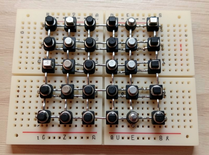
Plan the grid on paper first — decide how many rows and columns, and assign each to a pin. Then the build is repetitive but simple. Each switch connects to its row wire on one terminal and, through its diode, to its column wire on the other. The diode orientation matters and must be consistent across every switch: the banded end (the cathode) all face the same way relative to your scan direction, because that consistency is what blocks the back-feed. Pick a direction, wire one switch, test it, then replicate it exactly across the whole grid.
I solder the diode directly to the switch terminal to save space inside the enclosure, then run the column wires as a daisy chain down each line and the row wires across. Label your row and column wires with tape flags as you go; a 25-switch matrix is a forest of identical wires, and tracing an unlabeled one after the fact is miserable. A multimeter continuity check on each switch before you close the box catches the inevitable cold joint or reversed diode while it’s still easy to reach. Build slow, test as you go, and a 5×5 matrix is an afternoon, not a nightmare.
The firmware side
A matrix needs firmware that scans the grid, and the common Arduino approach pairs the Keypad library (which handles the row-column scanning) with the Joystick library (which reports the result as joystick buttons). The Keypad library maps each grid position to a key, and your sketch translates each key into a joystick button press. It sounds involved, but ready-made matrix sketches exist that you adapt by editing the row and column pin arrays and the grid dimensions. The firmware choices — Keypad-plus-Joystick versus GUI configurators that handle matrices for you — are compared in the button box firmware options guide.
Once the firmware reports the right button for each switch, you bind them in the sim exactly like any controller. These are digital inputs, so there’s no axis tuning involved — the curves and deadzones work applies only to your analog axes like the yoke and throttle, not the matrix.
Common matrix mistakes
The number one mistake is skipping diodes “to test it first” and then never adding them — the box seems fine until the first multi-switch press in flight. Wire the diodes from the start. The second is inconsistent diode orientation: one reversed diode creates a dead switch or a localized ghost that’s maddening to find. The third is forgetting that the encoders don’t go in the matrix — they need their own dedicated pins for clean direction reading, so budget those pins separately from your row-column count.
The last one is over-building. A 6×6 matrix reading 36 switches sounds glorious, but a panel that big takes real bench time and you’ll bind maybe two-thirds of it. Start with a 4×4 or 5×5, fly it, and expand only once you know which switches you actually reach for. That restraint is the same lesson behind the whole upgrade order doctrine — build for the realism you’ll use, not the panel that looks impressive in a photo.
Matrix versus a port expander
The matrix isn’t the only way to break the pin ceiling, and it’s worth knowing the alternative before you commit. A port expander chip — the MCP23017 is the common one — adds 16 extra input pins over a two-wire I2C connection to the Arduino. Each switch then wires direct to an expander pin, no diodes, no scanning, no ghosting to worry about. You can even chain several expanders for dozens of inputs while using only two pins on the Pro Micro.
So why does anyone bother with a matrix? Cost and parts count. A bag of diodes is cheaper than expander chips, and the matrix needs no extra ICs or breakout boards. The matrix also keeps everything in one familiar firmware path, while expanders need a library that reads the chip. My honest take from the bench: if you’re comfortable with the diode discipline, the matrix is the cheaper and more self-contained route for a one-off panel. If you hate the idea of soldering a diode to every switch and don’t mind one more library, an expander is the simpler wiring with fewer ways to introduce a ghost. Both end up looking identical to the sim — just another joystick — so the choice is purely about how you’d rather spend your bench time.
Frequently Asked Questions
What is a button box wiring matrix?
It is an arrangement of switches in rows and columns so a few pins read many inputs. The microcontroller scans one row at a time and reads the columns, identifying each switch by its grid position. A 4×4 matrix reads 16 switches on 8 pins.
Why do button box matrices need diodes?
To stop ghosting. When several switches are pressed at once, current can take a sneak path and register a switch nobody touched. A signal diode in series with each switch blocks that path so only intended presses register. The 1N4148 is the standard part.
How many switches can a matrix read?
Rows multiplied by columns. A 4×4 reads 16 switches on 8 pins, a 5×5 reads 25 on 10, and a 6×6 reads 36 on 12. The Joystick library caps the total reported at 32 buttons, so a 5×5 is the practical sweet spot for a full panel.
Which diode should I use for a button box matrix?
A 1N4148 small-signal diode. It is cheap, tiny enough to solder directly to a switch terminal, and sold in bags of a hundred. Orientation must be consistent across every switch, with the banded cathode end all facing the same way relative to the scan.
Do rotary encoders go in the matrix?
No. Encoders need their own dedicated pins so the firmware can read rotation direction cleanly from the order their two signals change. Budget those pins separately from your row and column count when planning a matrix panel.